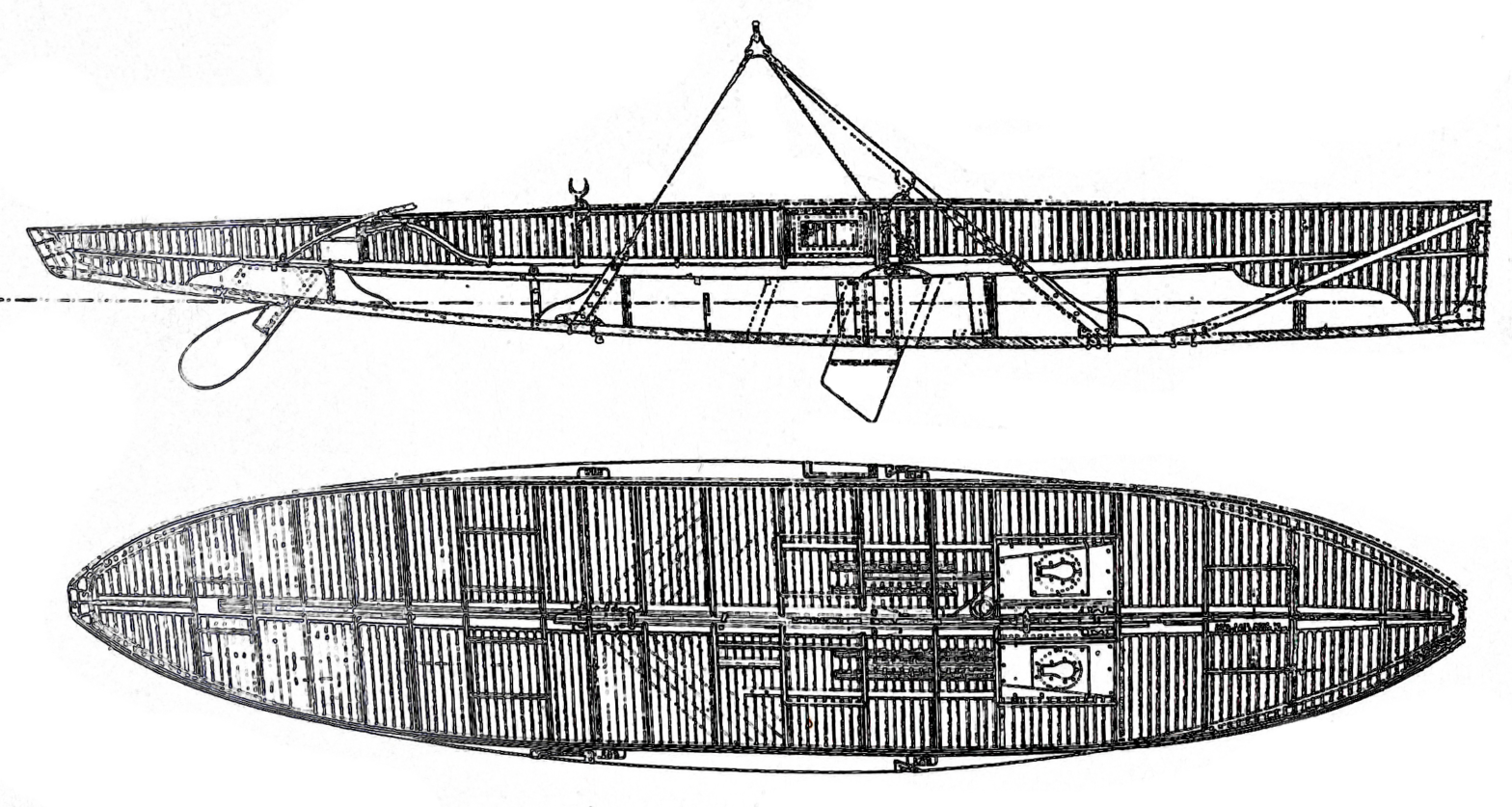
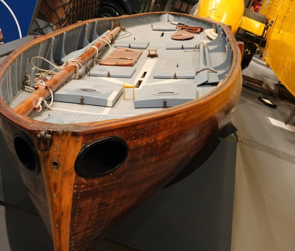
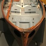
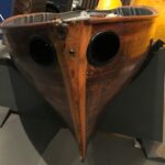
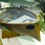
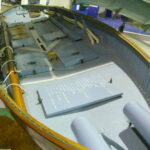
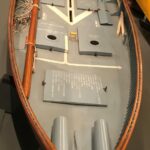
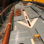
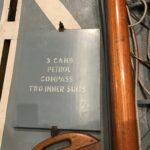
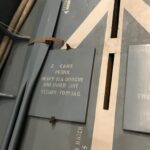
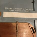
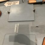
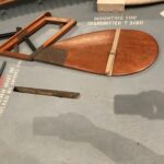
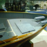
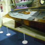
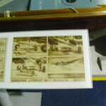
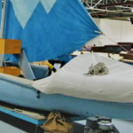
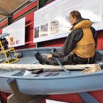
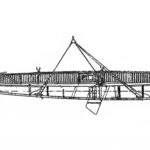
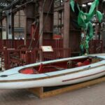
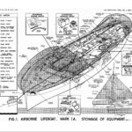
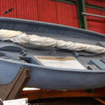
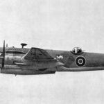
Airborne Lifeboats Mark I and IA – The majority of lifeboats built in the war were to the Mark I or IA design (473 of the approximately 800).
Uffa Fox became involved in the problem of Air Sea Rescue in 1942. After discarding several other schemes he used his skills to design a self-contained air-droppable lifeboat merging his designs for fast hulls with the ideas of Gp.CApt.Waring and Lieutenant Robb and input from suppliers of the extensive equipment involved.
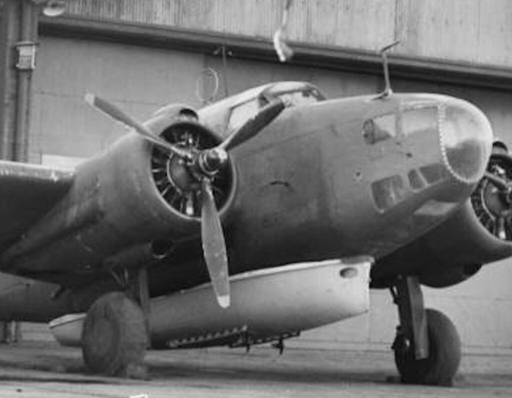
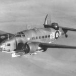
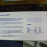
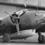
Initially, the Hudson was the only suitable aircraft the RAF could spare to carry the Mark I airborne lifeboat. The ageing Hudson placed restrictions on the dimensions of the lifeboat which also had to meet the design requirements developed with the RAF. Aspects of the design are shown in the table on the right. The lifeboat was dropped from a height of 700 feet (210m) and hit the water at up to 25mph.
After air tests, the first test drop was made from a Hudson in January 1943 and the first operational rescue drop in May of that year.
Only 71 lifeboats were built for the Hudson. Even before January 1943, the RAF had identified the larger Warwick bomber as a replacement for the Hudson. The Mark I lifeboat was modified to become the Mark IA fitted to the Warwick. 402 Mark IA lifeboats were built. The only modifications were to the top edges of the lifeboat and it’s mounting, to accommodate the different fuselage shape.
Design Issues
There Mark I / IA design was extremely successful, representing two-thirds of the wartime operational lifeboats. There were however some issues that arose due to the restrictions imposed by the Hudson.
- Propellers. These stuck down below the hull and were prone to get tangled by the many ropes from the parachutes and rescue lines.
- Size. The lifeboat was a tight fit for all of the aircrew of a ditched bomber and the gear and supplies required.
- Wooden construction did not fare well in hot climates – e.g. Mediterranean
The larger Warwick and then Lancaster aircraft allowed the Mark II design to solve the first two issues. The third was a key objective of the Mark III made in aluminium.
| Mark I | |
|---|---|
| Service | RAF |
| Aeroplane | I – Hudson IA – Warwick |
| Capacity (people) | 7 |
| Top Speed (knots) | 6 |
| Endurance (days) | 7 |
| Length overall | 23′ 2″ |
| Length waterline | 22′ 0″ |
| Beam | 5′ 5″ |
| Draft | 9″ |
| Displacement (tons) | 0.5 |
| Max All Up Weight (lbs) | 1700 |
| Constructions | Double skin mahogany |
| Engine | Two 4hp BPC ‘Middy’ 2-stroke. Protruding propellers. |
| Number Built | I – 71 IA – 402 |
| Operational | Feb 1943 |
| 1st Rescue Drop | 5th May 1943 |
| Notes | Size was limited by the low ground clearance of the Hudson. |
Notable Design Features
There are a number of notable features of the design. Click on the images below to enlarge.
Length
Canoe Stern
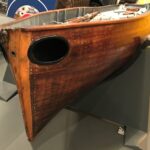
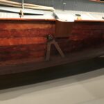
Tumblehome
Aerodynamics
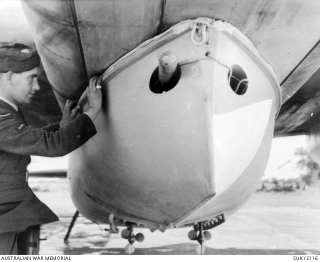
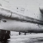
The lifeboat would impact the aircraft’s speed and handling. To minimise this the hull had to seal closely against the aircraft fuselage. The tumblehome outlined above helped and a soft rubber seal was fitted around the lifeboat gunwale (top edge) which was shaped to be a snug fit to the curves of the aircraft.
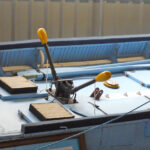
Bomb Hook

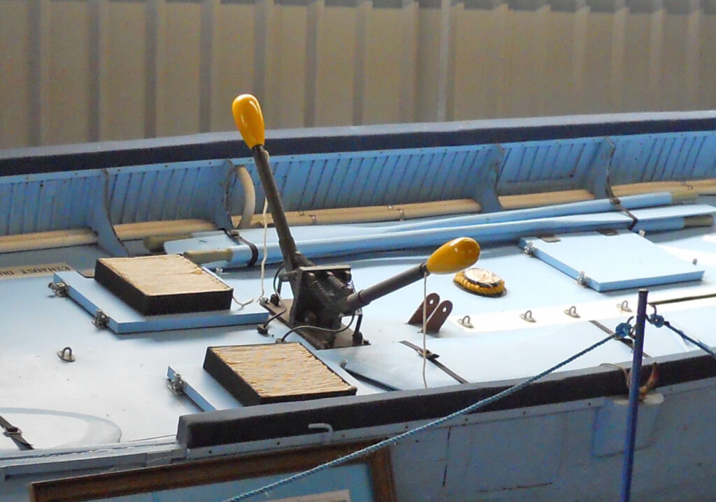
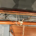
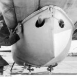
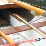
The lifeboat was attached to the aircraft by a single ‘bomb hook’, in the centre of the picture. (The bracket to the left is a mounting for the forward parachute sling.) This was fixed very strongly to the central keel case and hull and enabled a simple, bomb-like, quick release. The strong point so formed was also braced to the stem as reinforcement when being towed.
Controlled Descent
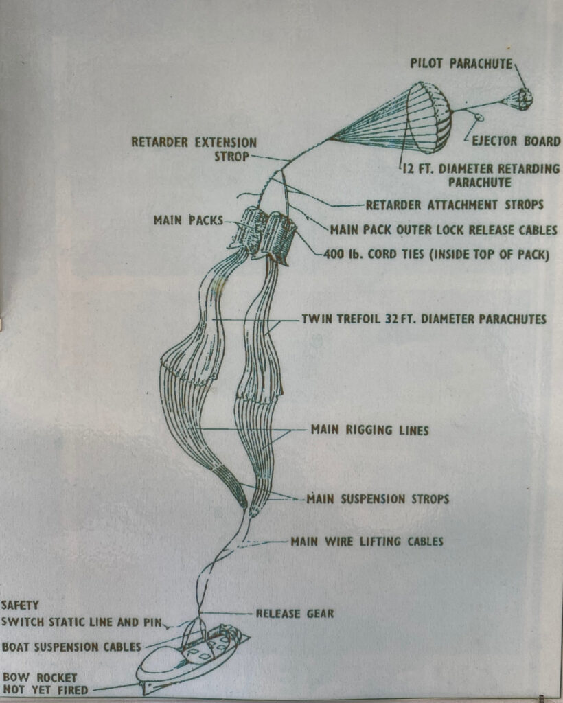
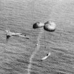
The lifeboat had to be slowed as it fell to around 25mph as it hit the water. Three parachutes deployed automatically as it was released. They were attached to wire strops attached to strong points in the hull arranged so that the lifeboat fell ‘bow-down’ at an angle of about 30 degrees to help reduce the shock of landing.
Rocket launched drogue

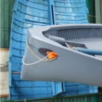
To prevent the lifeboat from being blown away from the ditched crew once on the water a rocket was fired from the bow to reply a ‘drogue’ – a piece of canvas like an underwater parachute. This held the bow into the wind and stopped it from blowing away. The rocket Wass in one of the tubes in the bow and the drogue in the other.
Self-Righting
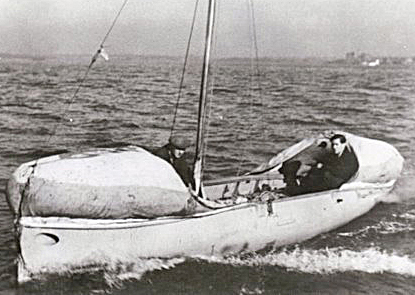
The lifeboat had to be able to operate in rough seas. The hull was necessarily low and the deck openings tightly sealed. To provide buoyancy inflatable bags were fitted at the front and back which would return the lifeboat upright were it to be capsized. These inflated automatically during the lifeboat descent.
Strong Hull
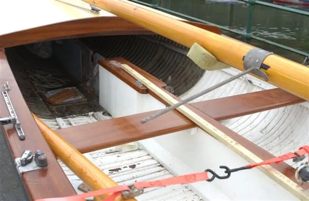
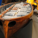
The hull had to be light and able to withstand the very great stresses of hitting the water at up to 25mph. Uffa employed two skins of mahogany planks, at an angle to each other, and closely spaced frames.
The hull was further strengthened by including a full-length ‘keel case’ running down the centreline. This box-like construction added great stiffness to the hull fore and aft.
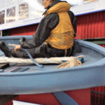
The close framing and central structure are exposed in this post-war conversion of a lifeboat to a yacht.
Rescue Lines
Engines at the front and to the side
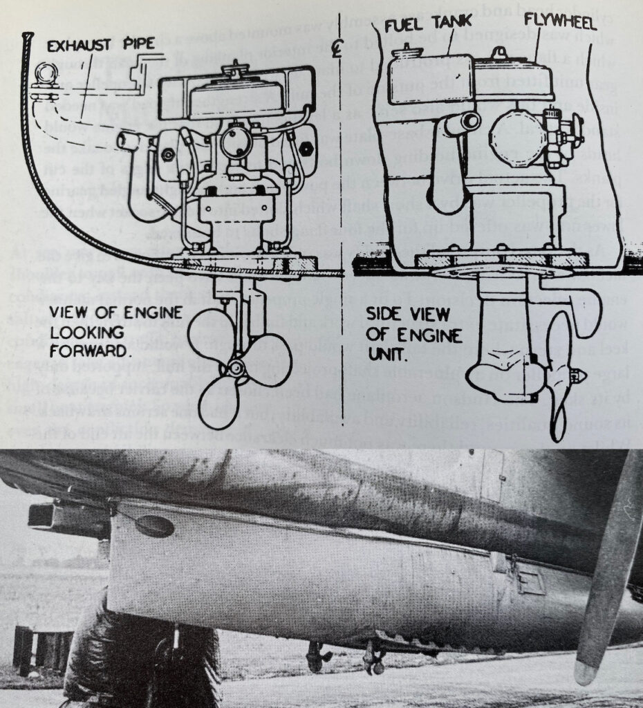
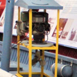
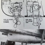
The only engines available at the time were the Britannia Middy, which drove the propellers through a leg fitted beneath the engine. The low ground clearance of the Hudson also meant there was little room for the propellers at the back of the lifeboat and they were positioned toward the front. Fitting either side of the central keel also increased ground clearance. (Interesting information about the Middy on this web page.)
Sailing ability

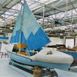
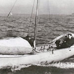
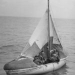
Engines were notoriously unreliable in boats so the boat had to be able to sail. Uffa drew on his extensive experience to provide an easily driven hull and a basic rig that could be operated by non-sailors. (It is notable that after the war many lifeboats were converted to pleasure yachts which proved very fast.)
Videos
| Type | Description | Designs |
|---|---|---|
| Video | Mark IA on a Canadian Warwick, including a drop, Huntley Film Archives A Canadian video which, at 2m49s, show a Mark I lifeboat being loaded and dropped on a Canadian Airforce plane, a Hudson (thanks Neville Cole for confirming this). A little misleading (at one point claiming ... | Mark I |
